

|
|
|
|
Electric Power ReferenceBy Gary Hoggard
| ||||||||||||||||||||||||||||||||||||||||||||||
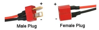 Deans Connector
These connectors are a good high-power plug for battery connections and brushed motor connections. They have a firm grip and excellent connectivity in all conditions. Battery leads will be terminated with a female Deans plug (to avoid short circuit when storing). |
In-line Gold Connectors
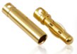
These come in a variety of diameters (2mm, 3mm, 3.5mm, 4mm & others). They are used to connect brushless motors to a speed controller (male plugs from the motor and female sockets on speed controller wires). Some people are now using these connectors also for battery leads (rather than Deans Plugs). It is important to completely cover the sockets in heat-shrink tubing to prevent accidental short-circuit. |
EC3 Connectors
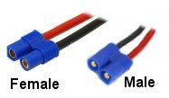
These are encased in-line connectors which are keyed to prevent reverse-polarity connections. They are becoming more popular for mid-power batteries as they are rated at 40 amps (although some manufacturers claim higher). The female plug commonly terminates the battery leads. |
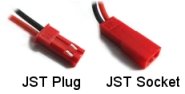 JST Connector
These are also known as "BEC" connectors and are generally for low current usage. They are often found on Park Flyers and other light-weight (low powered) aircraft. |
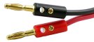 Banana Connector
The 4mm plug is commonly used to connect to battery charger output. It is common to have a charger cable with banana plugs at the charger end and a male Deans plug at the other end to connect to the battery. |
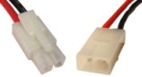 Tamiya Battery Connector
These are an inexpensive connector supplied with some battery packs. These connectors are not optimal for model aircraft and are best to change to Deans or in-line connectors. |
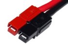 Anderson Powerpole Connector
The Anderson connectors are most commonly used in amateur radios for 12VDC connections. They come in a variety of sizes but the most common in RC use are the red and black connectors which are rated up to 45 amps. |
Before lithium compunds were used in batteries, the only sort of light-weight (relatived to the large lead-acid) batteries available were based on nickel-cadmium (NiCd). Later, nickel-metal-hydride (NiMH) compounds were used. NiCd batteries will delivery more instantaneous power (more "punch) than NiMH but suffer from battery "memory effect". Some technical information about NiCd and NiMH batteries is available on Wikipedia. Due to their weight, most RC enthusiasts prefer Lithium batteries over Nickel.
Lithium-based batteries are the prefered power source for RC flight. These batteries are much lighter that equivalent Nickel batteries and will also hold their charge much longer (weeks or months) without use. Also, unlike Nickel-based batteries, Lithiums do not need to be fully discharged before recharging. These come in three main types:
For model aircraft, the LiPo and LFP batteries are used. Care should be taken with Lithium-based batteries as they are violently combustable when exposted to air. This can happen when a battery over-heats due to over-charging or discharging past limits. LFP batteries have an advantage in that the compounds used avoid overheating at these limits (although cell voltages are slightly lower). Always use a BEC (see "Speed Controllers" below) with a cut-out of 3.0V with Lithiums.
Much has already been written about battery charges. The only note here is to stress that you should always use a smart charger (computer controlled) and it must be designed to charge the particular type of battery (NiCd, NiMH, LiPo or LFP) that you have.
| Battery Cell Quick Reference Chart | |||||
|---|---|---|---|---|---|
| Type | Low Discharge Voltage |
Nominal Voltage |
Max Charge Voltage |
Charge Current (see note below) |
Discharge Current (see note below) |
| NiCd | 0.1V | 1.2V | 1.8V | 0.1C - 3C | 1C - 10C+ |
| NiMH | 1.0V | 1.2V | 1.4V | ½C - 1C | 1C - 5C+ |
| LiPo | 3.0V | 3.7V | 4.2V | 1C | ½C - 30C+ |
| LiFePO4 | 2.8V | 3.3V | 3.6V | 1C | ½C - 30C+ |
NOTE: The charge and discharge currents shown are a "rule of thumb" only. Always follow the manufacturer's recommendations for exact ratings. The "C" rating means the nominal current rating for 1 cell. For example, a battery pack with cells of 2200mAh rating would have 1C of 2200mA (2.2 amps) and 3C of 6.6 amps.
To calculate the total power of a battery pack, voltage is multiplied by the number of cells and deliverable current (amperage) is based on the "C" rating. For example, a 3-cell ("3S") pack of 2200mAh LiPo cells rated at 25C would have a total voltage of 11.1V and deliver current up to (2.2 x 25) 55 amps.
Some useful links:
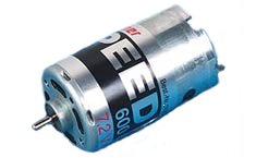
Brushed motors are older technology motors which connect the power to the motor coil via two carbon pads ("brushes"). These motors have two cables connected to them. Reversing the cables causes the motor to spin in the opposite direction. Because of the large amount of radio interference ("noise") generated by the brushes, small capacitors are usually connected across the terminals to reduce this noise.
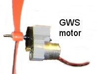
The size of brushed motors is commonly an equivalence to the Graupner brand "Speed" series. The Two most common being the "Speed 600" (for powered gliders, etc.) and the "Speed 400" (for smaller aircraft). For lighter park-flyers, a GWS brand (or equivalent) is used. This is a much smaller motor with at least a 3:1 ratio gear built in. You'll recognise these as the "orange prop" motors.
Wikipedia
describe the workings of this sort of motor quite well.
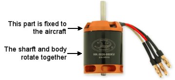
Brushless motors are often known as "outrunner" motors because most of the motor casing rotates around the commutator coil. Only one end of the motor remains stationary (see picture right), and this end is connected to the aircraft frame. Brushless motors have 3 connecting wires and must be controlled by a "brushless" speed controller.
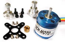
Some brushless motors are supplied with extra hardware to allow the propeller to be connected to the rotating body so that the motor may be connected to the forward side of the firewall. The picture at the left shows one of these.
When choosing the correct size brushless motor you need to be mindful of the thrust produced by the propeller that you connect to it. The current (amps) drawn by the motor will a function of the propeller used (the "load") and the voltage supplied by the battery. What this means is that a larger propeller (either in diameter, pitch or both) will put more load on the motor and thus it will require more current. The up-side is that the larger propeller gives more thrust and thus will lift a heavier aircraft. Increasing the voltage supply (e.g. going from a 2S to 3S lithuim battery) will allow the motor to spin faster and thus also give more thrust. Most manufacturers supply charts for each motor to assist you in choosing the correct battery, speed controller and propeller.
| Some useful links: |
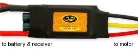
There are two types of electronic speed controllers (ESC) as there are two type of motors: brushed and brushless. Brushed speed controllers have two wires going to the motor and brushless have three. They are not interchangable. Most speed controllers also have a battery elimination circuit (BEC) built in. The BEC allows for the saving of battery power for the servos (aircraft control) when the battery runs low. It does this by either throttling back the motor or competely cutting it off (with an in-flight restart available).
When choosing a speed controller, a good rule-of-thumb is to pick its current rating at 50% higher than the peek current of the motor. For example, if your motor is rated for a peek current of 32 amps, then your speed controller will be at least 48 amps.
When it's all connected together, it may look something like...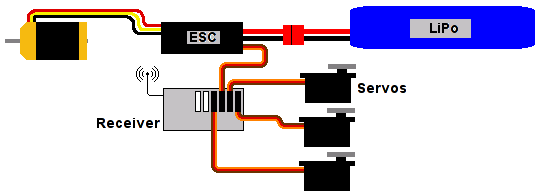
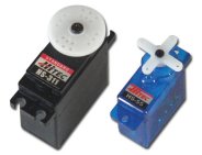
Servos are used to control the mechanics (control-surfaces, landing gear, etc.) of the aircraft and come in a variety of sizes and types. Manufacturers use terms such as "giant", "standard", "mini" and "micro" to help describe the overall size. The main two types differ in their internal gearing: nylon or metal. Metal gearing (and bearings) will generally be stronger but you also pay more for them. Most RC flight usage will be fine with nylon gearing.
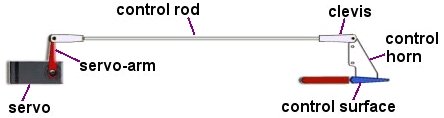
Most commonly, servos are connected to control-surfaces (ailerons, rudder and elevator) via linkages.
The components used in linkages are named below.
Radio control (RC) frequencies used in Australia fall into 4 bands: 29MHz, 36MHz, 40MHz (shortwave) and 2.4GHz (microwave). The shortwave bands require the transmitter and reciever to have crystals installed to lock the frequency to a particular channel. The 29MHz and 40MHz bands are rarely used for RC flight. The 2.4GHz band uses a combination of channel scanning and digital encoding to lock ("bind") the transmitter to a particular receiver so that interference with other transmitters will not occur.
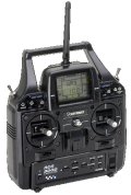
RC transmitters have two joystick controls which affect the first 4 channels (elevator, ailerons, throttle and rudder). There may also be extra switches and dials for extra channels. In Australia, we mostly use "Mode 1" controls which means that the throttle is on the right-hand joystick (Mode 2 has the throttle on the left and is used in USA).
All transmitters have a method of reversing the direction of the controls. The less-expensive models will have a set of slide-switches to do this. More complex ones will have this feature computer-controlled and a memory to save the settings against an aircraft name for later recall. A good deal of "mishaps" occur because the control reversal had not been checked before the aircraft was launched. Always go through your pre-flight check before launching.
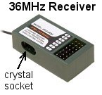
Receivers have an array of pins where servo plugs may be connected. The ESC is usually connected to channel 3 and supplies the power to the receiver and the other servos. Shortwave receivers have a long antenna wire and a socket where you must plug in a receiver crystal for it to work. For best reception, this antenna wire should be completely unwound. It normally runs the length of the fuselage and out the back of the aircraft.
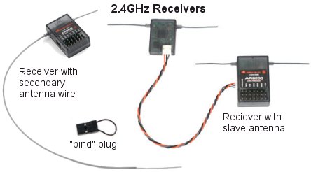
Microwave (2.4GHz) receivers do not require a crystal and have much shorter antennas (two). To assist reception, there will be either an extra-long second antenna wire or a complete secondary antenna (with both antenna wires). It is advisable to orient the secondary (antenna or wire) at 90-degrees to the first for best reception.
Shortwave receivers lock on to the transmitter with the set of crystals used. Microwave receivers must first be "bound" to the transmitter. A special bind plug (wire loop) is used to do this. Follow the instructions that came with your transmitter.
Some useful links:

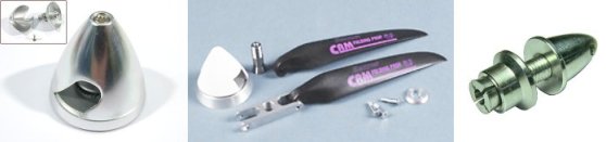
Model airplane propellers are either made from wood or a composite material. Composites are combinations of high strength fibers bound together by a polymer resin. Propeller sizes describe the overall diameter (or length) and the pitch. The sizes are usually in imperial measurements (inches). For example a "9x5" prop is 9 inches from end to end and moves forward 5 inches with each full rotation. Because of the fast rotation of the propeller, it is critical to have it well balanced and centred properly. Failure to do this will cause excessive wear on the motor.
A spinner is the device which holds the propeller and connects to the motor shaft.
It spins the propeller.
Spinners come in a variety of sizes to fit different size motor shafts and different types of propellers.
Common types are for fixed or folding propellers and some spinners come with a nose cone.
| © Copyright 2017 Gary Hoggard. | WebMaster: Tom Pecar |